A guidance-based docking system has been developed to localize short-range motion of the object of interest (Platform/ Manipulator/ End-effector of the Robot/ Autonomous Vehicle) into the required position with high-precision. Based on line-of-sight (LOS) method and the task-space sensor’s feedback, the LOS Task-Space sensing system has provided sufficient and accurate sensory data for the guidance-based motion planning of the Platform’s (object of interest) translation and rotation in multi-dimensional space. Meanwhile, a model-independent method has been proposed to dock the Platform’s (object of interest) to the high-precision without calibrating the model.
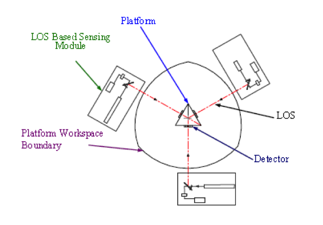
Figure 1. Three LOS-based Localization System Sketch
This project was expanded to use Neural-Network (NN)-based guidance methodology for path-planning to correct short range motion based on the line-of-sight indirect proximity sensory feedback.
In the project, the NN-model was established to generate the corrective motion commands to reduce the systemic motion errors of the vehicle. The errors were accumulated by a long-range of motions in an iterative manner. The
overall vehicle-docking methodology developed provides effective guidance that is independent of the sensing-system’s calibration model (modeless).
Later, Simulations were conducted with the 3-PSDs-based system. A multi-line-of-sight based guidance method for the six degree-of-freedom (DOF) localization of the platform (end-effector) was developed and applied on the meso-milling machine developed by CIM-lab to achieve sub-micron (0.1um) motion planning accuracy. Offsets were measured from the intersection of the three lines-of-sight on each position sensitive detectors (PSDs) mounted on the platform (end-effector). The errors will then generate corrective motions which guide the tool platform to its desired orientation and position.
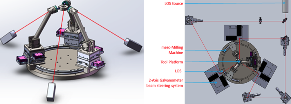
Figure 2. LOS-based 3PSD sensors Localization System Setup
From Fig 2, three laser-based LOS are used to define the desired pose (i.e., position and orientation) of the tool platform (end-effector). This guidance algorithm is utilized in a closed-loop system to reduce the measured accumulated errors of the platform after a long-range positioning to a minimum. The three PSDs detected the LOS hits as motion feedback and estimate the actual location of the tool platform (end-effector). The pose estimation algorithm is applied to position the platform iteratively to its desired location. The simulation of this system (3PSDsbased-LOS system) had been completed and proof to minimize the measured location errors to the desired tolerances in minimal number of iterations.
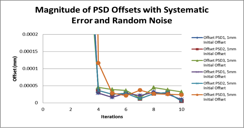
Figure 3. Magnitude of PSD Offsets with Systematic Error and Random Noise
(PSD Offsets require 4 iterations to converge below noise limits)
Currently, CIMLab is working on a single PSD LOS-based model dependent localization system and has achieved the same desired tolerances as 3 PSDs model.